Showing posts with label Section 2. Show all posts

Sunday, 25 March 2018

Section 2 d) Summary

Electrostatic charge is unmoving electric charge, caused by the transfer of electrons when two insulators are rubbed together. Usually, electric charge is allowed to flow in a current, through a conductor. Conductors have free charged particles that allow the current to carry the charge, but insulators do not, so the charge is static; it does not move.

Common conductors include metals, molten or aqueous ionic compounds, and carbon.
Common insulators include plastics such as rubber or acrylic, as well as air, paper and glass.

Like charges repel, and opposites attract. These forces of attraction and repulsion get weaker as distance is increased. This principle allows us to harness charges and use them for our benefit

Applications of electrostatic charge:

Inkjet printers
1. Tiny inkdrops become electrically charged as they are forced out of a small nozzle.
2. They travel past two plates, one positive and one negative. The drop is repelled by the like charge and attracted to the opposite charge, directing its landing spot on the paper.
3. The voltage across the plates is changed to direct each drop to form the image.

Photocopiers
1. A projection of your image is shone onto a positively charged image plate.
2. The light causes charge to leak away from some places.
3. Negatively charged powder (toner) is attracted to the positively charged parts of the plate, then transferred onto positively charged paper.
4. The paper is heated to seal the toner.

Problems and Dangers of electrostatic charge:

Problems

  • Screens attract dust as they get charged
  • Clothes cling to one another, and the body
  • Brushing hair can cause it to become statically charged and stand up

Dangers

  • Can build up in clouds and cause lightening, which can be dangerous
  • Buildup when fueling machinery could cause a spark, and an explosion
  • Touching an object with a large charge can give you a burn, or even kill you


Investigations into electrostatic charge:

Rod and cloth
1. Hold a polythene rod next to running water. Nothing will happen.
2. Rub the rod with a cloth, so friction causes electrons to transfer from the cloth onto the rod, causing both to become charged equally but oppositely.
3. Hold the rod next to the running water again. The stream will be bent, as like charges repel and opposite charges attract.

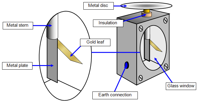
Gold leaf electroscope
1. Hold the object near the metal disc of a gold-leaf electroscope.
2. If the object is charged, this will induce a charge and cause the gold leaf to rise as it is repelled from the similarly-charged metal plate.

Suspended rods
1. Suspend a rod with a known charge, then hold your object near it.
2. If nothing happens, the object is not charged
3. If there is repulsion, the object has the same charge as the suspended rod.
4. If there is attraction, they have opposite charges.

Section 2 d) Key Words

Conductor: A material that allows current to flow through it due to free charged particles.

Earthed: When an object allows its charge to flow to earth and becomes neutral.

Earthing strap: A flexible metal strap that provides a path of least resistance for charge to travel down to earth.

Electrostatic charge: An electric charge that is not in motion; it is not flowing. Basically electricity without the current.

Insulator: A material that does not allow current to flow through it as it has no free charged particles.

Static Electricity: Unmoving electricity, electrostatic charge.

Section 2 d) Specification

2.19 identify common materials which are electrical conductors or insulators, including metals and plastics

Conductors:

  • Copper 
  • Lead
  • Molten or aqueous ionic compounds
  • Silver
  • Gold
  • Carbon

Insulators:

  • Rubber
  • Air 
  • Acrylic
  • Glass
  • Polyester
  • Paper


2.20 describe experiments to investigate how insulating materials can be charged by friction

Polythene and acetate rods experiment

  1. Rip up some pieces of paper and wave each of the rods near them. Nothing will happen.
  2. Rub the polythene rod with a duster. The electrons will transfer from the duster to the rod through friction, giving the rod a negative charge and the duster an equal positive charge. 
  3. Rub the acetate rod with a duster. The electrons will transfer from the acetate rod to the duster, giving it a negative charge and the rod an equal positive charge.
  4. Hold the rods near the paper individually. The pieces will be attracted to the rod. 
This can also be done by rubbing a balloon on a woolly jumper. The balloon can then attract small light objects, like ripped up paper or hair. 


2.21 explain that positive and negative electrostatic charges are produced on materials by the loss and gain of electrons

When rubbed together, friction is created between two objects. This force causes electrons to be transferred from on object to another, giving the objects equal but opposite charges.
These charges are electrostatic, meaning they do not flow.

2.22 understand that there are forces of attraction between unlike charges and forces of repulsion between like charges

Like charges repel, while opposite charges attract. These forces of attraction and repulsion weaken with distance.

2.23 explain electrostatic phenomena in terms of the movement of electrons

Electrostatic phenomena is the transfer of electrons from one object to another through friction. Positive particles never move; positive electrostatic charge is simply due to absence of negative particles.

2.24 explain the potential dangers of electrostatic charges, eg when fuelling aircraft and tankers

Electrostatic charges can cause sparks (this is what lightening is - buildup of electrostatic charge caused by friction between particles within the clouds that cause the bottom of the cloud to have a negative charge and the top to be negatively charged). These sparks can be very dangerous, for example when fueling a car or aircraft, a spark could cause an explosion. Because of this, electrostatic buildup in the tank is earthed by the metal fuel nozzle and earthing straps.

2.25 explain some uses of electrostatic charges, eg in photocopiers and inkjet printers.

Electrostatic charges can also be used to our advantage, for example in photocopiers and inkjet printers.

How an inkjet printer works:
  1. Tiny ink drops are forced out of a fine nozzle, the friction making them electrically charged.
  2. The charged drops are deflected as they pass through two oppositely charged metal plates.
  3. The drops are attracted to the plate with an opposite charge, and repelled from the similarly charged plate.
  4. The size and direction of the voltage across each plate is changed as each drop falls, causing them to land on different parts of the paper
How a photocopier works:
  1. An image of what you want to copy is projected onto a positively-charged image plate.
  2. Lighter parts of the image cause the charge to leak away in some parts of the paper.
  3. The positively charged parts of the image plate attract negatively charged black powder, which is then transferred onto positively charged paper.
  4. The paper is heated, causing the powder to stick.

Section 2 c) Summary

Series and parallel circuits

The current is the rate of flow of charge: I = Q/t
The voltage is the energy transferred per unit of charge: V = E/Q

In a series circuit, all of the components are connected in a line. This means the voltage is split between each of the components, but the current stays constant throughout, which is why ammeters are connected in series with components.
In a series circuit, the components are not individually controllable: they are either all on, or all off (e.g. Christmas lights). This can be disadvantageous as it means that if one of the components is broken, the whole circuit is disconnected and it can be difficult to find out which is faulty.


In a parallel circuit, the components are connected in 'branches'. Current is split between the 'branches', but each 'branch' receives the same voltage, which is why voltmeters are connected in parallel with components.
In a parallel circuit, the branches are individually controllable. A switch can be attached to each 'branch' and the components can be turned on and off as desired (e.g. different lights in a house). If one component breaks, the circuit will still work and the faulty component is easily located. 


Resistance and Resistors

Each component in a circuit has resistance; this can be thought of as like drag or friction opposing motion.
A component has greater resistance if it:

  • Emits heat (e.g. toaster)
  • Has a larger cross sectional area (of where the current flows)(e.g. thicker wires)
  • Total length of wires
  • Is made out of a less conductive material (e.g. copper has less resistance than carbon)
If there is more resistance in a circuit, less current will flow (or it will require more voltage to reach the same current). 
Variable resistors, fixed resistors, LDRs and thermistors are all components used to increase or decrease resistance in a circuit. 

Variable resistors allow the user to choose how much resistance they want, this is useful in dimmer switches for example. 

Fixed resistors are used to reduce the flow of electrons in a circuit, some appliances need a lower current to be able to work correctly. 


LDRs, or light dependent resistors, decrease in resistance when exposed to more intense light, and increase in dimmer light. These are used in burglar alarms and light intensity meters.

Thermistors are temperature dependent resistors, they increase in resistance when exposed to cooler temperatures. They are used in many appliances to maintain temperature, e.g. microwaves.

The resistance of a component can be determined by measuring the voltage and current across it in a circuit, and using this formula:
Voltage = Current x Resistance

The results can be graphed on an I-V graph (current on the y-axis, voltage on the x-axis), where the gradient is 1/R. These are the most important I-V graphs to know:

^ This is the I-V graph of a wire, or a resistor at a constant temperature. A steeper gradient means a lower resistance, and a shallower gradient means it has a higher resistance. This is according to Ohm's law: Electrical current is proportional to voltage and inversely proportional to resistance.

^ This is the I-V graph of a filament lamp. It is curved, because as the temperature of the metal filament increases so does the resistance.

^ This is the I-V graph of a diode. Diodes only allow current to flow in one direction; the resistance is very high in the opposite direction. The point at which the current increases dramatically is around 0.6 V.

To create a graph like this yourself, you must set up a circuit as shown:
Then, using the variable resistor to adjust the voltage, record the current across the component. Plot these points in an I-V graph, and draw a line of best fit.


Electrical symbols

Below is a guide on the basic components in an electrical circuit. There shouldn't be any other components that come up in the exam and most of these won't either.
The 10 most important are:

  • Cell
  • Battery
  • Filament lamp
  • Variable resistor, LDR, Thermistor
  • Power supply
  • Ammeter
  • Voltmeter
  • Diode
  • Switches
  • Fuse


Section 2 c) Key Words

Cell: Chemical power source, provides a circuit with electrical energy (basically a battery)


Current: The rate of flow of charge in a circuit. The movement of electrons from negative to positive.

Filament bulb: A light bulb containing a thin wire - a filament - that emits light when current passes through it.


LDR: Light-Dependent Resistor. Resistance decreases as light intensity increases.


LED: Light Emitting Diode. A component that emits light when current flows through in the forward direction. Used in traffic lights, digital clocks, remote controls, etc. No filament that can burn out.


Parallel circuit: A circuit connected with "branches". Voltage is constant over the different branches, but current is split. Allows individual control over components in the circuit.


Resistor: A component that has the sole purpose of opposing and decreasing the current flowing through a circuit.


Series circuit: A circuit where all of the components are connected in one line, and controlled together. Voltage is split across components, but current stays constant.


Thermistor: A resistor dependent on temperature. More heat = Less resistance, Less heat = More resistance. These are useful for temperature detection.


Guide to the most important electrical symbols plus some extra ones:


Section 2 c) Specification

2.8 explain why a series or parallel circuit is more appropriate for particular applications, including domestic lighting

Series circuits split voltage (potential difference) across the appliances, and maintain the same current (which is why we connect ammeters in series). Components in series cannot be controlled individually; they are all on or all off, no variation. This makes series circuits ideal for circuits such as that used in appliances such as Christmas lights, lamps, chargers, etc.

Parallel circuits split current, but maintain the same voltage across each component (which is why we connect voltmeters in parallel). Components in parallel circuits can each have individual switches, meaning they can be controlled individually. If one component breaks, the others all still work. This makes parallel circuits ideal for powering a room, because if this were in parallel it would require a component to be plugged into each socket for the lights to turn on. Power boards work in a similar way, you can plug as few or as many appliances in as you like and it will work the same.

2.9 understand that the current in a series circuit depends on the applied voltage and the number and nature of other components

The current of a circuit can be calculated by knowing voltage and resistance:
Current = Voltage / Resistance , or I = V/R
The voltage is applied by the power source, and the resistance is created by the components in the circuit. Each component has a different resistance, larger components, components requiring heating, and resistors generally have more resistance than a smaller component, for example a filament bulb.
The current can be calculated by adding up the resistance of all the components in the circuit, and dividing the applied voltage by it.

2.10 describe how current varies with voltage in wires, resistors, metal filament lamps and diodes, and how this can be investigated experimentally

Different components have different resistances, so by connecting the component in series with an ammeter, and changing the applied voltage, you can measure how the current varies. This can be recorded on an I-V graph, the gradient of the line being the 1/R.

2.11 describe the qualitative effect of changing resistance on the current in a circuit

When resistance is increased, less current will flow (or more voltage will be required to achieve the same current). This is because resistance directly opposes the flow of electrons.
Likewise, when resistance is decreased, more current will flow (or less voltage will be required to achieve the same current).
More components = more resistance, therefore more components = less current and less components = more current.

2.12 describe the qualitative variation of resistance of LDRs with illumination and of thermistors with temperature

LDRs, or light-dependent resistors, detect light and vary their resistance based on the light intensity. This is useful for devices such as burglar detectors. In bright light, the LDR has a very low resistance, but in darkness the resistance can be very high.


Thermistors work similarly to LDRs, but instead of detecting changes in light levels, they detect temperature changes. In hot conditions, the thermistor has a low resistance, whereas in cool conditions the resistance increases. This is useful for detecting temperature, for example in a car engine.


2.13 know that lamps and LEDs can be used to indicate the presence of a current in a circuit

You can test the connection of a circuit using a lamp or an LED. Just connect the bulb into the circuit, if it lights up, there is a current flowing.

2.14 know and use the relationship between voltage, current and resistance:
voltage = current × resistance
V = I × R

Voltage (in volts) = Current (in amperes) x Resistance (in ohms)
This relationship can be used to calculate current, resistance or voltage with simple rearrangement.


2.15 understand that current is the rate of flow of charge

I = Q / t
Meaning that current is the number of coulombs per second, the rate of flow of charge.

2.16 know and use the relationship between charge, current and time:
charge = current × time
Q = I × t

This relationship can be used to find the current, charge or time depending on how it is rearranged and what pieces of information you are given.
Q = Charge in Coulombs
I = Current in Amperes
t = Time in seconds

2.17 know that electric current in solid metallic conductors is a flow of negatively charged electrons

Electric current is the flow of charged particles, from negative to positive. These particles can be charged free-flowing ions, or electrons.
In a metallic structure, there is a sea of free electrons surrounding the positive ions which are fixed in place. This means that electric current is able to pass through; when the energy is applied the electrons flow from negative to positive in an electric current.

2.18 understand that:
  • voltage is the energy transferred per unit charge passed 
  • the volt is a joule per coulomb.
Voltage, or potential difference, is a very important part of learning about electricity and circuits, but what exactly is it? 
Voltage is defined as a measurement of the energy transferred per unit of charge passed, essentially the amount of energy in each unit of charge. 
A volt is the most common unit of measurement for potential difference, it is 1 joule of energy per coulomb of charge passed. 
E = V I t 
V = E / (I t)
Friday, 23 March 2018

Section 2 b) Summary

Mains electricity is the electricity supplied to each home. In the UK it is a.c. and 230V. A.c. means alternating current: it is constantly changing. By contrast, d.c. means direct current and does not change direction. This can be found in cell or battery powered circuits.

Current flowing though a circuit causes resistance. This can be calculated with the following formula:

Voltage = Current x Resistance
V= I R
(Remember this by calling it VIR pronounced veer)

Resistance causes a heating effect due to energy transfer. This increase in temperature also increases the resistance. This is used to our advantage in a variety of domestic situations
  • Fuses melt when the current is too high because it causes resistance and heating
  • Toasters toast bread with coils of high resistance wires that heat up
  • Kettles can heat water with a high resistance coil in the bottom of the appliance. 
Fuses and circuit breakers are chosen based on the current that should flow through the appliance with normal use. Fuses generally come in 3A, 5A, 7A and 13A. An appliance that would usually have a current of 2.3A flowing would use a 3A fuse, for example. 

Appliances are usually rated on power and voltage, so to calculate the necessary fuse we need to find out the current through this formula:

Power = Voltage x Current
P = I V
(Remember it by calling it PIV like pivot)

So an appliance with a rating of 1000W and 240V would be
1000 / 240 = 4.17 A
So we should use a 5 A fuse. 

Another important formula to know is this:

Energy transferred = Voltage x Current x Time
E = V I T
(Remember it by calling it EVIT like eviter, to avoid, in French)


Electrical circuits come with hazards that can cause injury or damage:


But there are often safety features put in place to ensure we are not hurt:


Section 2 b) Key Words

Alternating current: Current is constantly changing direction

Circuit breaker: An electrical safety device that will trip and break a circuit if too much current is flowing through. Use electromagnets to trip the switch and can be reset.

Conductor: A material that can easily transmit electrical energy, so aqueous/molten ionic compounds and metals, due to the free charged particles allowing current to pass through.

Double insulation: Two layers of insulation of a product, e.g. a plastic coated kettle. Greatly reduces chances of electric shock in event of fault.

Earth wire: Provides a path of least resistance to earth for high voltage currents in event of a fault.

Fuse: A thin wire that will melt when too much current flows through due to heating effect. Electrical safety device, requires replacement.

Insulator: A material that does not transmit electrical energy easily.

Mains electricity: A.c., 230V : the electricity that enters each home.

Resistance: Slows the flow in a circuit down. Causes a heating effect.

Section 2 b) Specification

2.2 understand and identify the hazards of electricity including frayed cables, long cables, damaged plugs, water around sockets, and pushing metal objects into sockets


2.3 understand the uses of insulation, double insulation, earthing, fuses and circuit breakers in a range of domestic appliances


2.4 understand that a current in a resistor results in the electrical transfer of energy and an increase in temperature, and how this can be used in a variety of domestic contexts

When there is an electrical current flowing through a wire, there is energy transfer which causes a heating effect. Higher currents cause more heat to be emitted, which means there is more resistance, causing less current to flow at the same voltage.
This effect can be used to our advantage, the principle is used in fuses: they melt when too much current is flowing because they heat up.
It can also be used in other appliances. Toasters and kettles often contain high resistance wires that heat up and boil our water or cook our toast. This was also used in old-style light bulbs, but since then more efficient ways have been developed.

2.5 know and use the relationship:
power = current × voltage
P = I × V
and apply the relationship to the selection of appropriate fuses

If an appliance has a power rating of 1000 W and 230 V, we can use this relationship to determine that the current is 1000 / 230, which equals 4.3 A. So in selecting a fuse, we would choose one that is close, but just slightly higher to normal operating current. In this case, a 5A fuse would be selected.

2.6 use the relationship between energy transferred, current, voltage and time:
energy transferred = current × voltage × time
E = I × V × t

If we know the current in an appliance is 2A and it is connected to a 4.5V battery, what is the energy transferred over 5 minutes?
2 x 4.5 x 5 x 60 = 2700 joules

2.7 understand the difference between mains electricity being alternating current (a.c.) and direct current (d.c.) being supplied by a cell or battery.

Alternating current means the current is constantly changing direction. Mains electricity is alternating current because it is easy to transport long distances, and easily converted using a transformer (advantageous because it allows current to be reduced and therefore less resistance will happen in power lines and therefore less energy lost)

^a.c. reading on an oscilloscope

Direct current means the direction of current does not change. This means it will provide a constant voltage.

^d.c. reading on an oscilloscope

Section 2 a) Key Words

Amperes: The unit of measurement for current

Charge: Whether there are more electrons or protons in a substance (negatively charged electrons vs positively charged protons) Positive and negative charges attract each other.

Coulombs: The rate of flow of current

Current: The rate of flow of electrical charge

Ohms: Unit of measurement of resistance

Potential difference: Also called voltage, it is the number of joules per coulomb, or the energy transferred per unit of current flowing per second.

Power: Rate of energy transferred.

Resistance: Anything that slows the flow in a circuit, increased by more components in series.

Voltage: Also called potential difference, it is the number of joules per coulomb, or the energy transferred per unit of current flowing per second.

Volts: Unit of measurement of voltage

Watts: Unit of measurement of power


Section 2 Specification

Section 2: Electricity

a) Units

2.1 use the following units: ampere (A), coulomb (C), joule (J), ohm (Ω), second (s), volt (V), watt (W).

b) Mains electricity

2.2 understand and identify the hazards of electricity including frayed cables, long cables, damaged plugs, water around sockets, and pushing metal objects into sockets

2.3 understand the uses of insulation, double insulation, earthing, fuses and circuit breakers in a range of domestic appliances

2.4 understand that a current in a resistor results in the electrical transfer of energy and an increase in temperature, and how this can be used in a variety of domestic contexts

2.5 know and use the relationship:
power = current × voltage
P = I × V
and apply the relationship to the selection of appropriate fuses

2.6 use the relationship between energy transferred, current, voltage and time:
energy transferred = current × voltage × time
E = I × V × t

2.7 understand the difference between mains electricity being alternating current (a.c.) and direct current (d.c.) being supplied by a cell or battery.

c) Energy and potential difference in circuits

2.8 explain why a series or parallel circuit is more appropriate for particular applications, including domestic lighting

2.9 understand that the current in a series circuit depends on the applied voltage and the number and nature of other components

2.10 describe how current varies with voltage in wires, resistors, metal filament lamps and diodes, and how this can be investigated experimentally

2.11 describe the qualitative effect of changing resistance on the current in a circuit

2.12 describe the qualitative variation of resistance of LDRs with illumination and of thermistors with temperature

2.13 know that lamps and LEDs can be used to indicate the presence of a current in a circuit

2.14 know and use the relationship between voltage, current and resistance:
voltage = current × resistance
V = I × R

2.15 understand that current is the rate of flow of charge

2.16 know and use the relationship between charge, current and time:
charge = current × time
Q = I × t

2.17 know that electric current in solid metallic conductors is a flow of negatively charged electrons

2.18 understand that:

  • voltage is the energy transferred per unit charge passed 
  • the volt is a joule per coulomb.


d) Electric charge

2.19 identify common materials which are electrical conductors or insulators, including metals and plastics

2.20 describe experiments to investigate how insulating materials can be charged by friction

2.21 explain that positive and negative electrostatic charges are produced on materials by the loss and gain of electrons

2.22 understand that there are forces of attraction between unlike charges and forces of repulsion between like charges

2.23 explain electrostatic phenomena in terms of the movement of electrons

2.24 explain the potential dangers of electrostatic charges, eg when fuelling aircraft and tankers

2.25 explain some uses of electrostatic charges, eg in photocopiers and inkjet printers.

Section 2 a) Specification

2.1 use the following units: ampere (A), coulomb (C), joule (J), ohm (Ω), second (s), volt (V), watt (W).

Ampere or Amps is used to describe the current in an electrical current.
Coulombs are used to describe the rate of flow of charge, in other words it's how many amps per second. (current / time)
Joules are used to measure quantities of energy transferred (voltage x current x time)
Ohms are used to measure resistance (voltage / current)
Seconds measure time.
Volts measure potential difference.
Watts measure power (current x voltage)

Section 4 b) Summary

The nine types of energy important to learn are: Electrical energy Light  Sound Kinetic Nuclear Thermal  Gravitational Chemical ...